To build this Smart Home Monitoring system, follow these steps:
- Gather all the required components listed below.
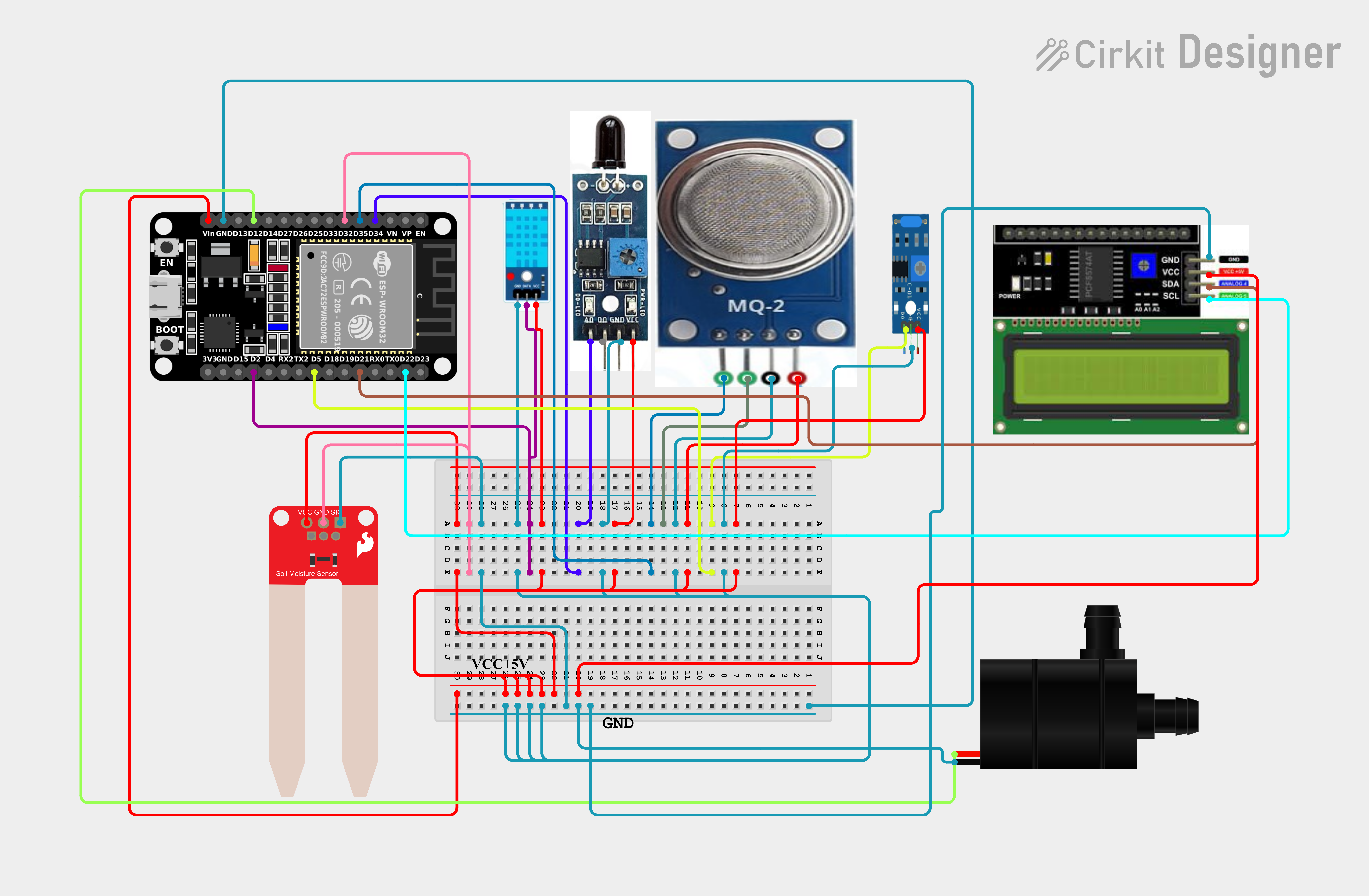
- Connect the ESP32 microcontroller to all sensors as per the circuit diagram.
- Connect the DHT11 sensor to the ESP32 for temperature and humidity monitoring.
- Upload the provided source code to the ESP32 using the Arduino IDE.
- Test the setup to ensure all components are working correctly.
- Develop a Website to interface with the ESP32 for remote monitoring.
The making process involves several key steps:
Step 1: Component Assembly
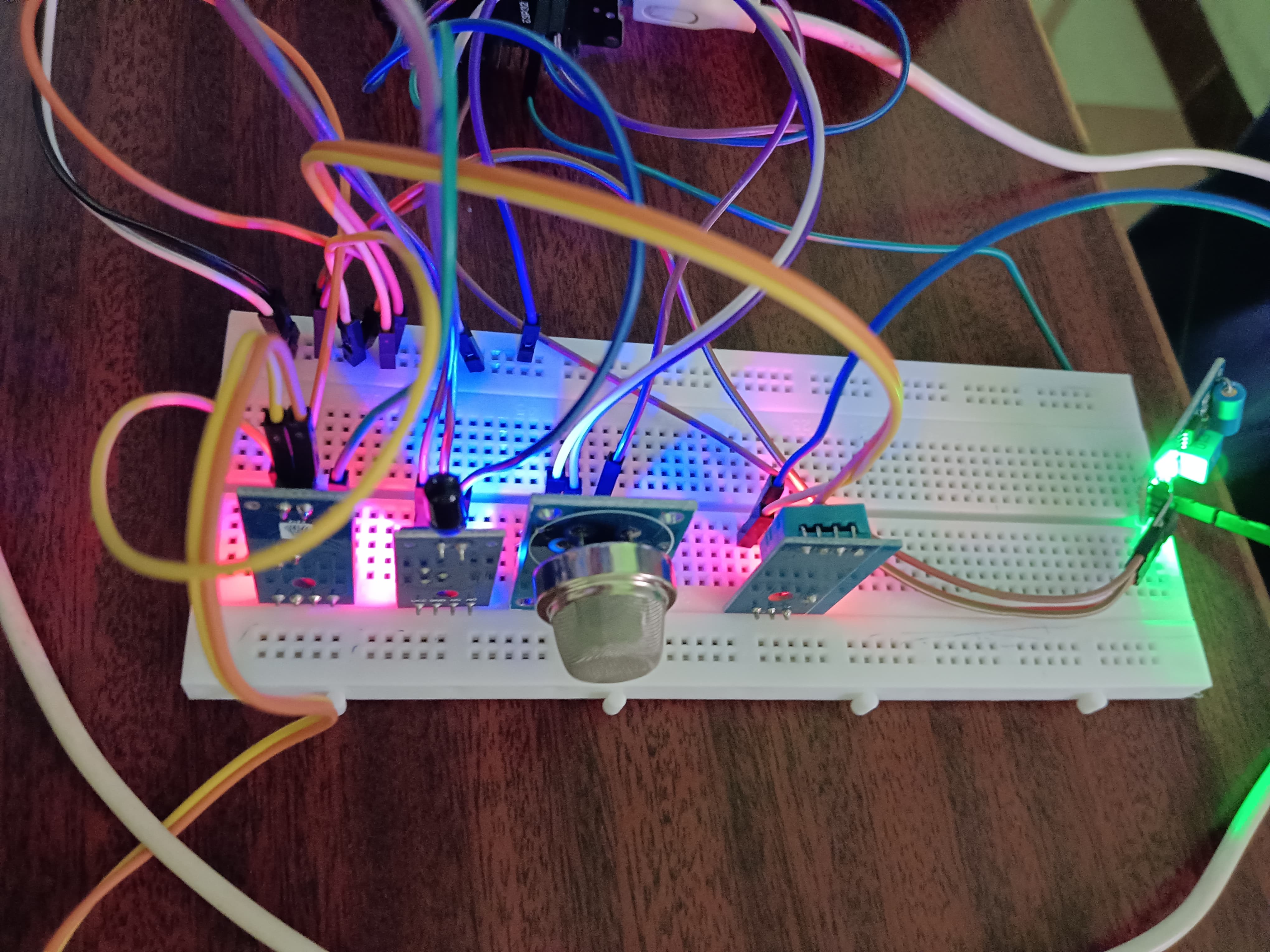
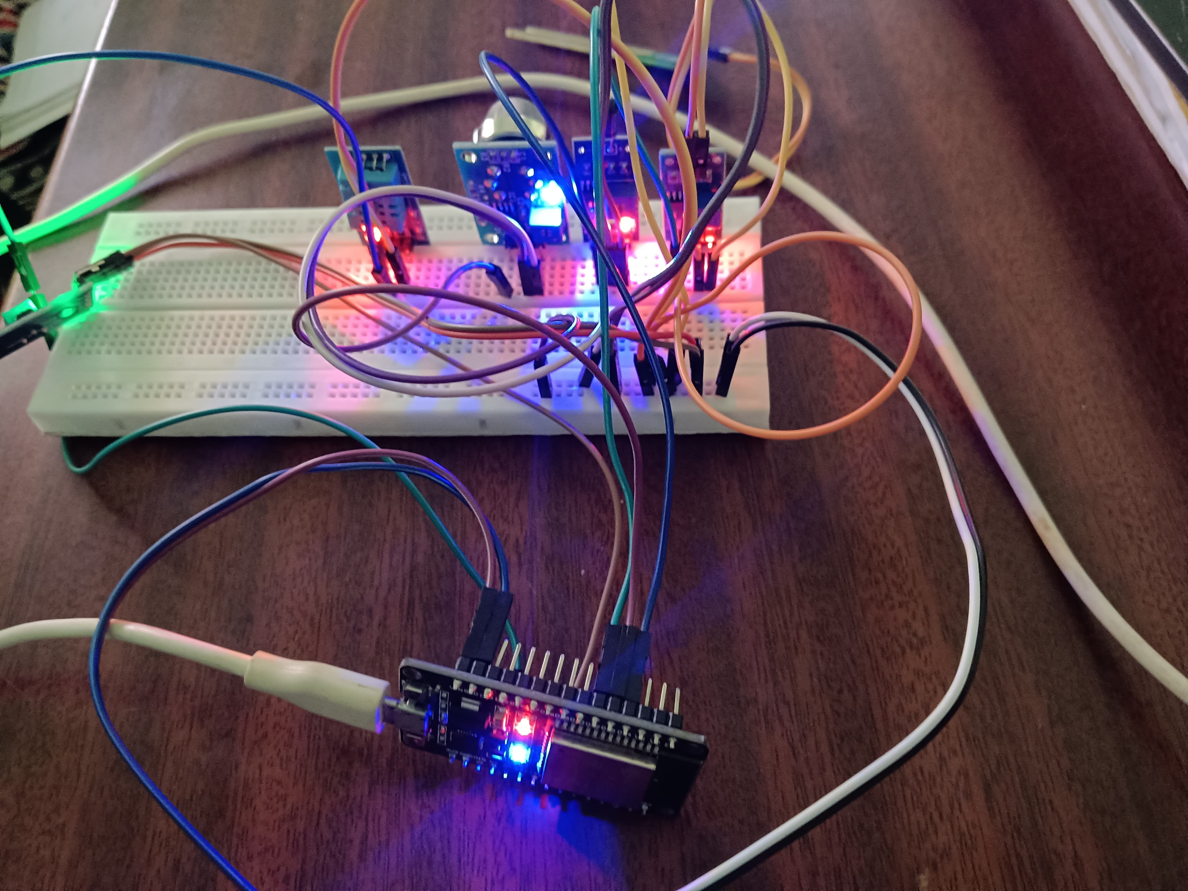
Begin by gathering all the necessary components, including ESP32 microcontroller, sensors (fire, MQ2, vibration sensor, soil moisture sensor), 5V relay, water pump, and a 16x2 LCD. Refer to the circuit diagram to assemble these components ensuring secure connections without any loose wires.
Step 2: Programming the ESP32
Program the ESP32 using Arduino IDE to read data from the sensors (fire, MQ2, vibration sensor, soil moisture sensor). Implement logic to control the water pump through the 5V relay based on soil moisture readings. Also, program the ESP32 to display sensor data on the 16x2 LCD for offline monitoring.
Step 3: Testing and Calibration
After programming, conduct thorough testing to ensure all components are functioning correctly. Verify sensor readings (fire, MQ2, vibration, soil moisture) and ensure the ESP32 accurately controls the water pump via the relay. Calibrate sensors if necessary and make adjustments to code or wiring.
Step 4: Website Development
Develop a web interface to monitor real-time data from the ESP32. Utilize suitable web development technologies (HTML, CSS, JavaScript) and frameworks (e.g., Bootstrap) to create an intuitive dashboard. Ensure the website integrates seamlessly with the ESP32 to display sensor readings and control functionalities remotely.
With these steps, you can successfully build a comprehensive home monitoring system using ESP32 and various sensors, enhancing the efficiency and convenience of managing your home environment.
.png)